一、Introduction to NE555
Introduction to NE555 Timer IC:
Overview:
The NE555 is a popular and versatile integrated circuit (IC) timer commonly used in a wide range of timing and pulse generation applications. Known for its simplicity, reliability, and flexibility, the NE555 is a fundamental component in electronic circuits.
Features:
- Timer Functionality: Capable of generating accurate time delays and pulses.
- Versatile: Supports various modes of operation, including monostable and astable.
- Adjustable Timing: Resistor and capacitor values determine output timing.
- Low Power Consumption: Suitable for battery-operated applications.
- Stable Operation: Provides consistent timing accuracy across temperature ranges.
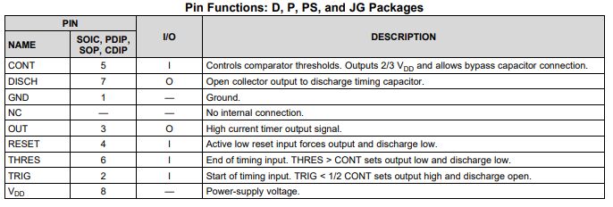
Pin Configuration:
- 8-Pin DIP Package: Typically consists of 8 pins for easy integration into circuit designs.
- VCC: Positive power supply terminal.
- GND: Ground terminal.
- Trigger (TRIG): Input to initiate the timing cycle.
- Output (OUT): Provides the timed output signal.
- Reset (RESET): Resets the timer and stops the output.
- Control Voltage (CV): Allows optional external voltage control.
Main Modes of Operation:
- Astable Mode: Generates a continuous square wave.
- Monostable Mode: Produces a single pulse based on external triggers.
Applications:
- Timing Circuits: Delays, oscillators, and pulse generation.
- Pulse Width Modulation (PWM): Controlling the width of pulses in various applications.
- Precision Timing: Supporting accurate timed events in electronic systems.
- Tone Generation: Creating audio tones in musical applications.
Working Principle:
- RC Timing Network: An external resistor-capacitor combination determines the timing intervals.
- Comparator Operation: Internal comparators trigger output transitions based on the set thresholds.
- Bistable Multivibrator: Switches between stable states in response to trigger signals.
Benefits:
- Ease of Use: Simple integration and configuration in circuit designs.
- Cost-Effective: Provides timing functions without the need for complex circuitry.
- Reliability: Offers stable and predictable timing characteristics.
- Wide Operating Voltage Range: Supports diverse voltage requirements in applications.
Variants:
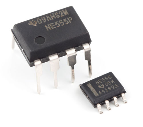
- NE555P: Standard 555 timer IC in a DIP package.
- LM555: Similar functionality with slight variations in performance.
- SE555: High-temperature variant for demanding environments.
The NE555 timer IC is an essential component in electronics, favored for its reliability and wide applicability in timing and pulse generation circuits. Whether used in simple timing applications or complex pulse modulation systems, the NE555's flexibility and consistency make it a valuable tool for engineers and hobbyists alike. Understanding its modes of operation and applications enables efficient utilization of its features in diverse electronic projects.
二、Introduction to TLC555
Introduction to TLC555 Timer IC:
Overview:
The TLC555 is an enhanced version of the classic NE555 timer IC, offering improved performance and additional features while maintaining compatibility with existing 555 timer circuits. It serves as a versatile timer IC commonly used in various timing applications in the field of electronics.
Features:
- Enhanced Performance: Offers lower power consumption and higher accuracy compared to the NE555.
- Wide Supply Voltage Range: Supports operation from a broad range of voltages for flexibility in different applications.
- Adjustable Timing Range: Provides versatile timing options for diverse circuit needs.
- Stable Operation: Ensures consistent timing accuracy across temperature variations.
- Low Threshold and Trigger Currents: Enables operation in low-power, battery-sensitive applications.
Pin Configuration:
- The TLC555 typically comes in an 8-pin DIP package and features pins similar to the NE555, including VCC, GND, TRIG, OUT, RESET, DISCH, and CV.
Key Differences from NE555:
- Lower Power Consumption: Ideal for battery-operated devices.
- Improved Stability: Offers better performance in terms of timing accuracy and temperature range.
- Reduced Trigger Currents: Allows for operation in low-power and energy-efficient applications.
Main Modes of Operation:
- Astable Mode: Generates a continuous square wave output.
- Monostable Mode: Produces a single pulse output based on external trigger input.
Applications:
- Timing Circuits: Precise time delay and pulse generation.
- Pulse Width Modulation (PWM): Controlling pulse widths in various applications.
- Frequency Generation: Producing clock signals and oscillations.
- Sensor Applications: Interfacing with sensors for signal processing.
Benefits:
- Low Power Consumption: Suitable for energy-efficient designs.
- High Accuracy: Offers precise timing capabilities for critical applications.
- Flexibility: Supports a wide range of timing configurations and applications.
- Compatibility: Designed to work as a drop-in replacement for the standard NE555 timer IC.
Use Cases:
- Portable Electronics: Suitable for low-power devices that require timing functions.
- Automotive Applications: Used for timing circuits in automotive electronics.
- Embedded Systems: Integrated into microcontroller-based projects for timing tasks.
Variants:
- TLC555ID: Surface-mount version for compact designs.
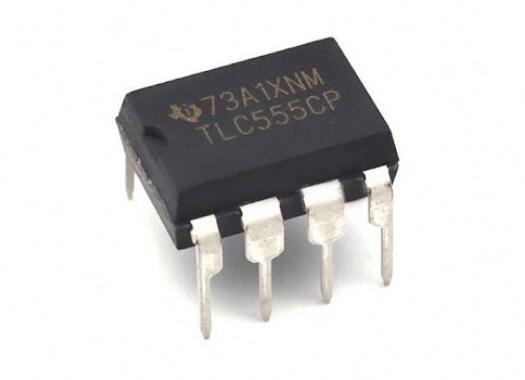
- TLC555CP: Standard DIP package for easy prototyping.
The TLC555 timer IC is a versatile and improved version of the classic NE555, offering enhanced performance, lower power consumption, and improved stability for a wide range of timing applications in electronics. Its compatibility with existing 555 timer circuits makes it a convenient choice for engineers and hobbyists looking to upgrade their designs with improved timing capabilities and efficiency.
三、Main features of NE555 and TLC555
Main Features of NE555 and TLC555 Timer ICs:
NE555 Timer IC:
- Versatility: The NE555 is a classic timer IC known for its versatility and widespread use in various timing applications.
- Ease of Use: It is simple to integrate into circuit designs and offers straightforward timing functions.
- Stable Operation: Provides consistent and reliable timing accuracy across a range of conditions.
- Cost-Effective: Offers timing functionalities without the need for complex additional circuitry.
- Applications: Widely used in timing circuits, pulse generation, oscillators, and more in electronic projects.
TLC555 Timer IC:
- Enhanced Performance: The TLC555 offers improved performance compared to the NE555 with lower power consumption and higher accuracy.
- Low Power Operation: Designed for low-power and battery-sensitive applications, making it ideal for energy-efficient designs.
- Wide Supply Voltage Range: Supports operation from a broad range of voltages, adding flexibility for different applications.
- Improved Stability: Ensures accurate and stable timing across various temperature ranges and operating conditions.
- Compatibility: Designed as a drop-in replacement for the NE555 while offering enhanced features for modern applications.
Both the NE555 and TLC555 timer ICs are valuable tools in electronics for implementing timing functions and pulse generation. The NE555 is a reliable classic with a long history of use, while the TLC555 represents an enhanced version with improved performance features tailored for modern low-power and precise timing applications. When selecting between the two, consider factors such as power consumption, accuracy requirements, and the specific needs of your project to choose the most suitable timer IC for your application.
四、Main parameters of NE555 and TLC555
Main Parameters of NE555 and TLC555 Timer ICs:
NE555 Timer IC:
- Supply Voltage (Vcc):
- NE555 typically operates within a range of 4.5V to 15V.
- Operating Temperature Range:
- The NE555 works reliably across a temperature range of 0°C to 70°C.
- Timing Capacitance (C):
- The timing capacitor range for the NE555 is typically in the nanofarad (nF) to microfarad (µF) range.
- Timing Resistance (R):
- The timing resistor range for the NE555 is typically in the kilohm (kΩ) to megohm (MΩ) range.
- Output Current (Iout):
- NE555 can typically sink or source up to 200mA of current.
- Threshold Voltage (Vth) and Trigger Voltage (Vtrig):
- NE555 operates with threshold and trigger voltages typically around 1/3 and 2/3 of Vcc, respectively.
TLC555 Timer IC:
- Supply Voltage (Vcc):
- TLC555 operates within a similar range as NE555, typically from 2V to 15V.
- Operating Temperature Range:
- TLC555 often has an extended temperature range compared to NE555, operating from -40°C to 125°C.
- Timing Capacitance (C):
- Timing capacitor values for the TLC555 are typically within the same nanofarad (nF) to microfarad (µF) range as NE555.
- Timing Resistance (R):
- The timing resistor range for the TLC555 is also similar, falling in the kilohm (kΩ) to megohm (MΩ) range.
- Output Current (Iout):
- TLC555 can typically source or sink up to 100mA of current.
- Threshold Voltage (Vth) and Trigger Voltage (Vtrig):
- Operating thresholds for the TLC555 are usually around the same levels as the NE555, set at 1/3 and 2/3 of Vcc.
Comparison:
- Power Consumption: TLC555 typically consumes less power compared to NE555.
- Temperature Stability: TLC555 commonly offers better stability over a wider temperature range.
- Output Current Capability: NE555 often has higher current sourcing/sinking capability compared to TLC555.
- Voltage Range: TLC555 can usually operate at lower supply voltages than NE555, making it more suitable for low-power applications.
When considering whether to use the NE555 or TLC555 in a design, comparing these key parameters can help in selecting the appropriate timer IC based on the specific requirements of the application, such as operating conditions, power consumption constraints, and timing precision needed.
五、Pin configuration of NE555 and TLC555
•NE555
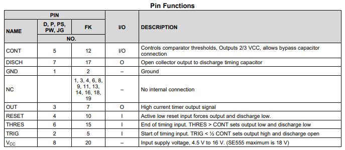
•TLC555
六、Application of NE555 and TLC555
Applications of NE555 and TLC555 Timer ICs:
NE555 Timer IC:
- Pulse Generation:
- NE555 is commonly used to generate square wave pulses in various electronic circuits.
- Precision Timing:
- It is utilized in applications where precise timing intervals are required, such as in timers and clocks.
- Oscillator Circuits:
- NE555 can be configured as an astable multivibrator for generating clock signals and oscillations.
- PWM Generation:
- Pulse Width Modulation (PWM) circuits can be implemented using NE555 for applications like motor speed control.
- Monostable Multivibrators:
- Used to generate single output pulses triggered by external events, suitable for applications like debounce circuits.
- LED Flashers:
- NE555 can drive LEDs in flashing or blinking circuits for lighting effects.
TLC555 Timer IC:
- Low-Power Applications:
- Due to its lower power consumption, TLC555 is ideal for battery-operated devices and energy-efficient designs.
- Temperature-Critical Applications:
- The improved stability of TLC555 makes it suitable for applications requiring timing precision across varying temperatures.
- Sensor Interfaces:
- Used to interface with sensors for signal processing where accurate timing is essential.
- Automotive Electronics:
- Suitable for various timing circuits in automotive applications such as lighting systems or alarms.
- Portable Electronics:
- TLC555 can be used in timing circuits for portable devices or wearable technology.
- Precision Timing Applications:
- Ideal for applications requiring precise timing control, such as in data communication systems or instrumentation.
Common Applications for Both ICs:
- Educational Projects:
- NE555 and TLC555 are popular choices for learning about timing circuits and basic electronics in educational settings.
- Prototyping:
- Used in prototyping electronic circuits due to their ease of use and wide range of applications.
- DIY Projects:
- Hobbyists often use these ICs in DIY electronic projects ranging from simple timers to more complex pulse generation systems.
- Control Systems:
- Integrated into various control systems for timing and synchronization purposes.
- Audio Applications:
- Utilized in audio circuits for generation of tones, oscillators, and metronomes.
Both the NE555 and TLC555 timer ICs find applications in a diverse range of electronic projects and circuits due to their versatility, reliability, and ease of use. Understanding the unique features and performance characteristics of each IC can help in selecting the most appropriate one for specific applications based on factors such as power consumption, timing precision, and environmental conditions.
七、Electrical characteristics of NE555 and TLC555
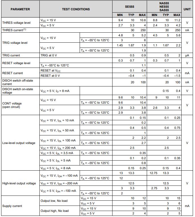
Electrical Characteristics of NE555 and TLC555 Timer ICs:
NE555 Timer IC Electrical Characteristics:
-
Supply Voltage (Vcc):
- Typically operates within a range of 4.5V to 15V.
-
Operating Temperature Range:
- Recommended operating temperature range is 0°C to 70°C.
-
Output Current Capability (Iout):
- Can typically sink or source up to 200mA of current.
-
Threshold and Trigger Voltages (Vth, Vtrig):
- Threshold voltage (Vth) and trigger voltage (Vtrig) are usually around 1/3 and 2/3 of Vcc, respectively.
-
Output High Voltage (VOH) and Output Low Voltage (VOL):
- The output high voltage (VOH) and output low voltage (VOL) levels are specified with respect to the supply voltage.
-
Timing Capacitance (C) and Timing Resistance (R) Range:
- Timing capacitor values typically range from nanofarads (nF) to microfarads (µF), while timing resistor values range from kilohms (kΩ) to megohms (MΩ).
-
Power Consumption:
- Consumes moderate power depending on the operating frequency and duty cycle.
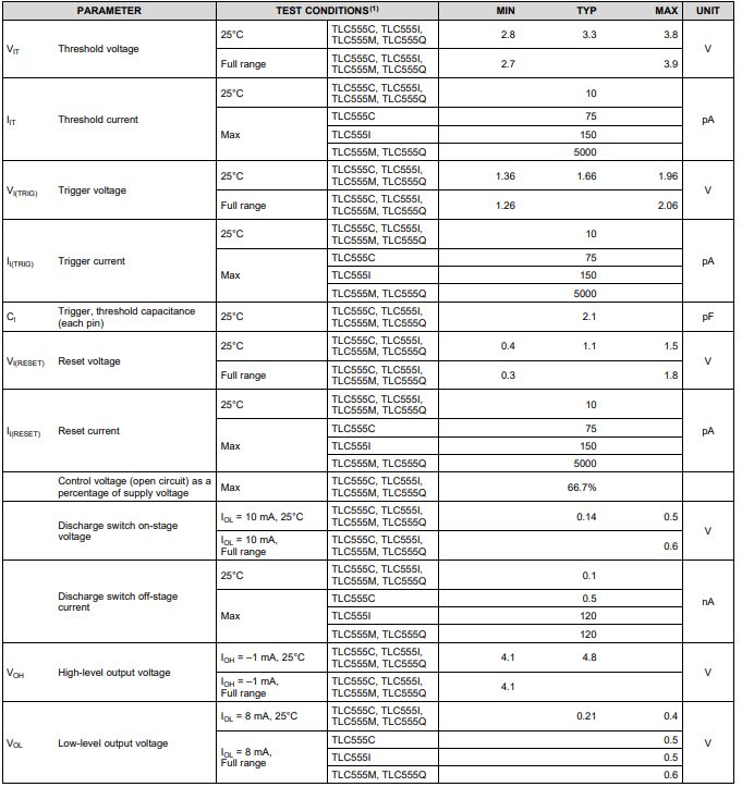
TLC555 Timer IC Electrical Characteristics:
-
Supply Voltage (Vcc):
- Operates within a range typically from 2V to 15V, offering a lower starting voltage option compared to NE555.
-
Operating Temperature Range:
- Extended operating temperature range from -40°C to 125°C for more extreme conditions.
-
Output Current Capability (Iout):
- Can typically source or sink up to 100mA of current.
-
Threshold and Trigger Voltages (Vth, Vtrig):
- Similar to NE555, usually around 1/3 and 2/3 of Vcc for threshold and trigger voltages.
-
Output High Voltage (VOH) and Output Low Voltage (VOL):
- Output voltage levels relative to the supply voltage with specified maximum and minimum values.
-
Timing Capacitance (C) and Timing Resistance (R) Range:
- Similar to NE555, timing capacitor and resistor values fall in the ranges of nanofarads to microfarads and kilohms to megohms, respectively.
-
Power Consumption:
- TLC555 is known for its lower power consumption compared to NE555, making it suitable for low-power applications.
Comparison and Selection:
- Power Efficiency: TLC555 typically consumes less power than NE555.
- Temperature Range: TLC555 has a wider operating temperature range suitable for more extreme conditions.
- Output Current Capability: NE555 generally has a higher current sourcing/sinking capability compared to TLC555.
- Voltage Range: TLC555 can operate at lower supply voltages, making it more energy-efficient in certain applications.
Understanding the electrical characteristics of NE555 and TLC555 is crucial for selecting the most appropriate timer IC for a given application based on factors like operating voltage, temperature requirements, power consumption constraints, timing precision, and current sourcing/sinking capabilities.
八、The difference between NE555 and TLC555
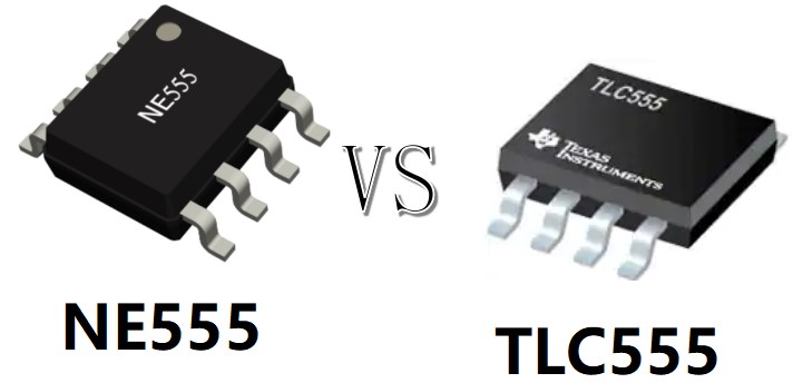
The NE555 and TLC555 are both popular timer ICs, with the TLC555 being an improved version of the classic NE555. Here are some key differences between the two ICs:
NE555 Timer IC:
- Classic Design: The NE555 is a widely used and well-established timer IC known for its versatility and simplicity.
- Reliability: It offers reliable performance and has been a staple in the electronics industry for many years.
- Operating Voltage Range: Typically operates within a supply voltage range of 4.5V to 15V.
- Temperature Range: Suitable for operation within 0°C to 70°C.
- Output Current: Can typically sink or source up to 200mA of current.
- Simple to Use: The NE555 is straightforward to implement in various circuit designs.
- Cost-Effective: Provides basic timing functions without the need for complex additional circuitry.
TLC555 Timer IC:
- Enhanced Performance: The TLC555 is an improved version of the NE555 with added features and better performance characteristics.
- Low Power Consumption: Designed for low-power applications, making it more energy-efficient than the NE555.
- Extended Temperature Range: Operates over a wider temperature range, typically from -40°C to 125°C, making it suitable for more extreme conditions.
- Lower Supply Voltage: Can operate at lower supply voltages, typically from 2V to 15V, offering better efficiency in low-power designs.
- Output Current: Can typically source or sink up to 100mA of current.
- Improved Stability: Offers better timing accuracy and stability across varying conditions.
- Drop-In Replacement: Designed as a drop-in replacement for the NE555 in many applications, making it easy to upgrade designs without significant changes.
Summary of Differences:
- Power Consumption: The TLC555 consumes less power compared to the NE555, making it more suitable for low-power applications.
- Temperature Range: The TLC555 has an extended operating temperature range, ideal for applications in harsh environments.
- Voltage Range: The TLC555 can operate at lower supply voltages, offering energy efficiency benefits.
- Output Current: The NE555 has a higher current sourcing/sinking capability compared to the TLC555.
- Compatibility: While the TLC555 can often be used as a direct replacement for the NE555, it offers enhanced features and performance improvements.
When choosing between the NE555 and TLC555 for a specific application, consider factors such as power consumption, temperature requirements, operating voltage range, and timing precision needed to select the most appropriate timer IC for your project.
九、Common points between NE555 and TLC555
The NE555 and TLC555 timer ICs share some common points despite their differences. Here are some common aspects between the NE555 and TLC555 timer ICs:
Common Points Between NE555 and TLC555 Timer ICs:
-
Timer Functionality: Both the NE555 and TLC555 are timer ICs that are widely used for generating accurate time delays, pulses, oscillations, and timing circuits.
-
Pin-compatible: The TLC555 is designed to be a drop-in replacement for the NE555, meaning that the pin configuration and function are similar between the two ICs. This allows for easy substitution in many applications without significant changes to the circuit design.
-
Timing Capacitance and Resistance Ranges: Both ICs typically work with timing capacitor values ranging from nanofarads to microfarads and timing resistor values ranging from kilohms to megohms. This commonality in timing component ranges allows for flexibility in designing various timing circuits.
-
Threshold and Trigger Voltages: Both ICs have similar threshold and trigger voltages, set around 1/3 and 2/3 of the supply voltage. This consistency in voltage levels simplifies designing circuits that utilize these timing parameters.
-
Output Functionality: Both the NE555 and TLC555 can drive external components through their outputs, enabling the generation of accurate timing signals and controlling other circuit elements.
-
Ease of Use: Both ICs are relatively easy to use and integrate into circuit designs. They are popular choices for beginners and experienced engineers alike due to their simplicity and versatility in timing applications.
-
Widespread Acceptance: The NE555 and TLC555 have been extensively used in a wide range of electronic projects across various industries, showcasing their reputation and reliability in the field.
-
Versatile Applications: Both ICs find applications in areas such as pulse generation, precision timing, oscillators, frequency dividers, LED flashers, pulse-width modulation, and more, highlighting their versatile nature.
While the NE555 and TLC555 have differences in technical specifications and performance characteristics, these common points demonstrate their shared utility as fundamental timing components widely used in electronics for a variety of applications. Whether designing simple projects or more complex circuits, both ICs offer reliable timing functions with a proven track record in the industry.
Frequently Asked Questions
1.What are the common problems during use of NE555?
The external circuit connection is incorrect, the capacitor or resistance value is improperly selected, and the power supply voltage is unstable; the trigger pulse input is incorrect, the external component is faulty, and the power supply voltage is lower than the working requirements of the NE555; the external component is connected incorrectly, and the power supply voltage is unstable.
2.Under what circumstances might the supply voltage of the TLC555 affect its performance?
When the supply voltage of the TLC555 is lower than its specified minimum operating voltage, it may not work properly or the output may be unstable. Therefore, it is necessary to ensure that the power supply voltage is within the specified range, usually 2V to 15V. Changes in the supply voltage may cause instability in the TLC555 output level. Under extreme supply voltage conditions, the output level may not reach the specified high or low level.
3.How accurate is the NE555 timer?
For sub-1% accuracy, the NE555 timer is ideal. For better than 0.1% accuracy, consider digital or crystal technology. If the power supply voltage changes quickly relative to the timing period, the NE555 sometimes has output jitter problems.
4.What type of load can the output pin of TLC555 drive?
The output pins of the TLC555 can be used to drive CMOS and TTL logic gates because these gates generally have higher input impedance and require less load on the output. The TLC555 can be used to drive low-power LEDs, but attention needs to be paid to current limits and voltage requirements to ensure use within the specified parameters.