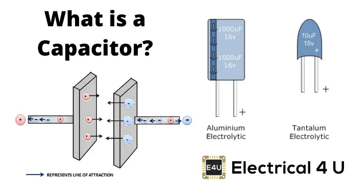
A capacitor is a passive electronic component that stores and releases electrical energy in an electrical field. It is a fundamental component in electronic circuits and is commonly used for various purposes, including filtering, energy storage, tuning circuits, decoupling, and timing applications.
Key Characteristics of Capacitors:
-
Functionality: Capacitors store electrical energy in the form of an electric field and release it when needed.
-
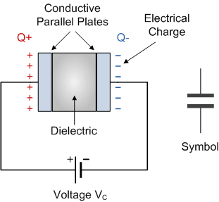
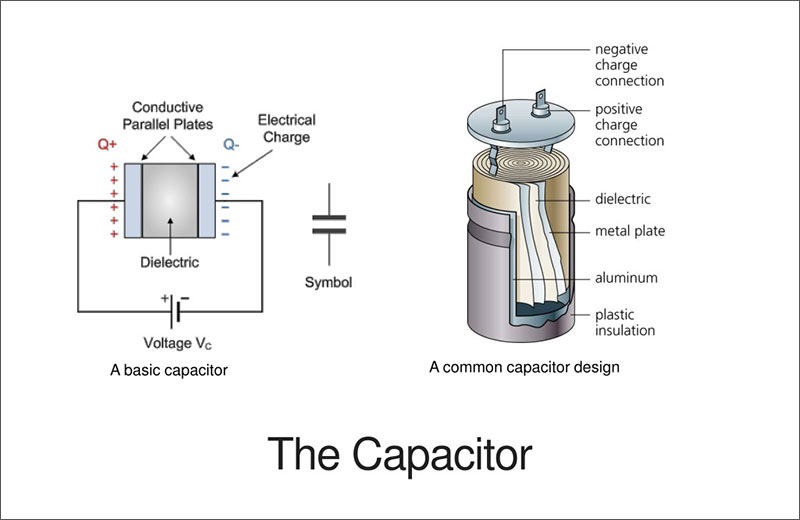
Symbol: The symbol for a capacitor in circuit diagrams is two parallel lines representing the plates with a gap between them.
-
Construction: Capacitors consist of two conductive plates separated by an insulating material known as the dielectric.
-
Dielectric: The dielectric material between the plates determines the capacitor's characteristics such as capacitance value and voltage rating.
-
Capacitance: Measured in farads (F), capacitance indicates the amount of charge a capacitor can store per volt of applied voltage.
-
Polarization: Some capacitors are polarized, meaning they have a specific orientation for correct voltage polarity, while others are non-polarized.
-
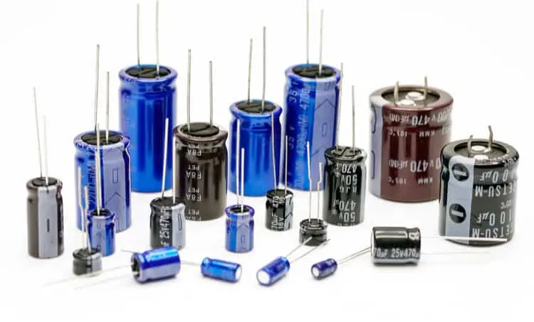
Types: Capacitors come in various types such as electrolytic, ceramic, tantalum, film, and others, each with distinct properties and applications.
-
Applications: Used in power supply filtering, decoupling, signal coupling, timing circuits, smoothing voltage ripples, and energy storage.
Capacitor Working Principle:
- When a voltage is applied across the capacitor, it stores electric charge on its plates, creating an electric field between them.
- Capacitors resist changes in voltage, so they can smooth out voltage variations in a circuit.
- Capacitors can release the stored energy when needed, discharging quickly or slowly based on the circuit's requirements.
Types of Capacitors:
-
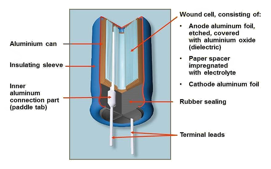
Electrolytic Capacitors: Known for high capacitance values and relatively large physical size. They are polarized and commonly used in power supply circuits.
-
Ceramic Capacitors: Small in size, stable, and available in a wide range of capacitance values. They are non-polarized and suitable for high-frequency applications.
-
Tantalum Capacitors: Compact, have a high energy density, and are polarized. They are used in compact electronic devices.
-
Film Capacitors: Made of plastic film as the dielectric, offering good stability and reliability. They are used in various applications.
-
Variable Capacitors: Their capacitance can be adjusted manually or electronically, making them suitable for tuning circuits.
Capacitor Applications:
- Filtering: Capacitors can filter out noise from power supplies or signal lines.
- Decoupling: Used to decouple different parts of a circuit to prevent interference.
- Timing Circuits: Capacitors are integral in setting time constants for various circuits.
- Energy Storage: Capacitors store energy that can be quickly discharged when needed.
Capacitors play a crucial role in electronics by storing and releasing electrical energy, filtering signals, and performing various other functions critical to the operation of electronic circuits. Their varied types and properties make them versatile components in a wide range of applications.
Overview of Capacitor Symbol
The symbol for a capacitor in circuit diagrams is a widely recognized representation used to indicate the presence of a capacitor in an electronic circuit. Here is an overview of the capacitor symbol commonly used in circuit diagrams:
Capacitor Symbol Overview:
- Symbol: The symbol for a capacitor consists of two parallel lines representing the plates of the capacitor with a gap between them. It looks like two horizontal lines side by side with plates on either end:
- Polarized Capacitor: For polarized capacitors like electrolytic capacitors, an arrow or "+" sign is added to indicate the positive terminal of the capacitor. The longer line represents the positive plate, and the shorter line indicates the negative plate. The arrow or "+" denotes the positive plate:
- Non-Polarized Capacitor: In the case of non-polarized capacitors like ceramic or film capacitors, the symbol is typically a simpler representation without an arrow or polarity indication:
Additional Annotations:
- Labeling: The capacitance value is often indicated next to or within the symbol.
- Schematic Placement: In circuit diagrams, the capacitor symbol is positioned wherever a capacitor is placed within the circuit, typically between two connecting lines.
Capacitor Variations:
- Variable Capacitors: Variable capacitors have a different symbol to denote their adjustable nature. They typically have various straight lines indicating their plates.
Application Notes:
- Orientation: The orientation of the capacitor symbol may vary based on the circuit design or diagram layout.
- Connectivity: Connections to other components or nodes in the circuit are made to the ends of the capacitor symbol.
Importance in Schematics:
- Clarity: The standardized capacitor symbol aids in quickly identifying the presence of capacitors in circuit diagrams.
- Consistency: Following standard symbols ensures uniformity and clarity in electrical schematics, aiding in effective communication and understanding between engineers and technicians.
- Design Understanding: Capacitor symbols help in visualizing circuit layouts and understanding the role of capacitors in electronic systems.
Summary:
The capacitor symbol, with its distinctive depiction of two parallel lines representing the conductive plates separated by a dielectric, is an essential element in circuit diagrams. Its representation conveys the presence of a capacitor, its polarity in the case of polarized capacitors, and aids in understanding the role of capacitors in electronic circuits through standardized schematic notation.
Types of Capacitor Symbols
In electronic circuit diagrams, different types of capacitors may be represented by various symbols, depending on their characteristics and properties. Here are the symbols used to depict some common types of capacitors:
1. Standard Capacitor Symbol:
- The standard symbol for a generic capacitor is represented by two parallel lines indicating the plates with a gap between them. This symbol is used for non-polarized capacitors in general circuit diagrams.
2. Polarized Capacitor Symbols:
Polarized capacitors have distinct symbols to indicate their polarity. Common polarized capacitors include electrolytic capacitors.
a. Electrolytic Capacitor Symbol:
- Electrolytic capacitors have a symbol indicating their polarity. The longer line represents the positive plate, and the shorter line indicates the negative plate. An arrow or "+" sign is often added to show the positive terminal.
b. Tantalum Capacitor Symbol:
- Tantalum capacitors are also polarized, and their symbol is similar to that of an electrolytic capacitor, denoting the polarity with a specific indication for the positive terminal.
3. Variable Capacitor Symbol:
- Variable capacitors, often used for tuning applications, have symbols that indicate their adjustability. The symbol usually includes various straight lines representing the plates.
Additional Notes:
- Capacitor symbols may also include capacitance values next to or within the symbol.
- The orientation of the capacitor symbol may vary based on the circuit diagram layout and conventions.
- Different symbols help in quickly identifying the type of capacitor used in a circuit, especially when polarity or specific characteristics need to be highlighted.
Importance of Symbol Variations:
- Identification: Different symbols for various capacitor types aid in quickly identifying the type of capacitor used in the circuit.
- Polarity Indication: Symbols for polarized capacitors clearly show the polarity to avoid incorrect orientation during circuit design and assembly.
- Clarity in Schematics: Using specific symbols for different capacitor types enhances the clarity and understanding of schematics among engineers, technicians, and designers.
By utilizing these varied capacitor symbols in circuit diagrams, designers and engineers can effectively communicate the type, characteristics, and polarity of capacitors used in electronic circuits, ensuring accurate implementation and troubleshooting when necessary.
Capacitor Symbol Meaning
The symbol used to represent a capacitor in electronic circuit diagrams holds specific meanings and information pertinent to its function and characteristics. Here is a breakdown of the meanings conveyed by the capacitor symbol:
Capacitor Symbol Meaning:
-
Capacitor Plates:
- The two parallel lines represent the plates of the capacitor. These plates store electrical charge when a voltage is applied across the capacitor.
-
Gap Between Plates:
- The gap between the plates signifies the dielectric material. The dielectric is an insulating material that separates the conductive plates of the capacitor.
-
Physical Structure:
- The symbol reflects the physical structure of a capacitor where two conductive surfaces are separated by an insulating material.
-
Capacitance Storage:
- Capacitors store electrical energy when charged, and the symbol indicates this energy storage capacity within the circuit.
-
Charge-Discharge Cycle:
- The symbol visually represents the charge-discharge cycle of a capacitor. When charged, it can release stored energy when required.
-
Simplified Representation:
- The symbol provides a simplified representation of a capacitor within a circuit diagram, aiding in clear communication and understanding of the circuit layout.
Specific Variations in Symbol:
-
Polarized Capacitor Symbol:
- For polarized capacitors like electrolytic capacitors, additional markings like an arrow or "+" sign denote the positive terminal to ensure correct polarity in the circuit.
-
Variable Capacitor Symbol:
- Variable capacitors have symbols that indicate their adjustability, typically featuring multiple straight lines representing the adjustable plates.
Purpose of the Symbol:
-
Identifying Capacitors: The symbol allows for quick identification of capacitors within a circuit diagram, highlighting their presence and locations.
-
Polarity Information: Symbols for polarized capacitors specifically indicate the polarity to prevent incorrect installation in the circuit.
-
Circuit Design Clarity: The symbol enhances the clarity of circuit diagrams by clearly representing the presence and function of capacitors within the overall circuit layout.
Design Intent:
-
Functionality Focus: The capacitor symbol emphasizes the component's ability to store and release electrical energy, a fundamental aspect of its operation in electronic circuits.
-
Visual Communication: Through a standardized symbol, engineers and technicians can easily interpret and convey the presence and purpose of capacitors in circuit designs.
Summary:
The capacitor symbol in circuit diagrams serves as a visual representation of the capacitor's function, structure, and role within an electronic circuit. By conveying essential information like capacitance storage, physical structure, and polarity requirements, the symbol plays a crucial role in aiding the understanding, design, and troubleshooting of electronic circuits involving capacitors.
Capacitor Symbols on a Multimeter
In a multimeter, the symbols used to represent capacitors may vary slightly depending on the specific model and manufacturer. However, commonly used symbols for capacitors on multimeters typically include "F" or "µF" to indicate capacitance measurement settings. Here is an overview of how capacitance is typically represented on a multimeter:
Capacitor Symbols on a Multimeter:
-
Capacitance Measurement Function:
- Multimeters capable of measuring capacitance have a designated setting that allows users to measure the capacitance of capacitors in a circuit.
-
Capacitance Units:
- Capacitance values are usually displayed in farads (F) or microfarads (µF) on the multimeter screen when measuring capacitors.
-
Symbols Used:
-
The symbols you may encounter on a multimeter to represent capacitance measurement settings include:
-
"F": This symbol denotes farads, the standard unit of capacitance.
-
"µF" or uF: Represents microfarads, a more common unit for capacitance values encountered in electronics.
-
-
Range Selection:
- Multimeters often allow you to select a range for capacitance measurements. These settings enable you to measure capacitors within a specific range of values accurately.
-
Function Selection Switch:
- To measure capacitance, users typically need to turn the function selection switch on the multimeter to the capacitance measurement setting. This switch may have a dedicated symbol for capacitance measurements.
-
Reading Display:
- The multimeter screen will show the capacitance value in the chosen units (farads or microfarads) when the measurement is taken.
Interpretation on a Multimeter:
-
Unit Conversion: Some multimeters automatically convert capacitance readings between farads and microfarads based on the measurement range and value.
-
Accuracy Display: The multimeter display provides the measured capacitance value, enabling users to determine the capacitance of the capacitor under test accurately.
Importance of Capacitance Measurement on a Multimeter:
-
Diagnostic Tool: Capacitance measurement on a multimeter is crucial for troubleshooting circuits, identifying faulty capacitors, and verifying correct capacitor values in electronic systems.
-
Maintenance and Repair: Technicians and engineers use multimeters to ensure capacitor health, functionality, and proper capacitance values in various electronic devices and circuits.
Summary:
The symbols used on a multimeter to represent capacitance measurement settings, such as "F," "µF," or uF, are integral for accurately measuring the capacitance of capacitors in electronic circuits. Capacitance measurement functions on a multimeter aid in diagnostics, maintenance, and repair tasks by providing insights into the health and performance of capacitors within electronic systems.
Variations in Capacitor Symbols
In electronic circuit diagrams, variations in capacitor symbols may exist to differentiate between different types of capacitors based on their properties or characteristics. Here are some common variations in capacitor symbols:
1. Standard Capacitor Symbol:
- The standard symbol for a generic capacitor consists of two parallel lines representing the plates with a gap between them. This symbol is typically used for non-polarized capacitors in general circuit diagrams.
2. Polarized Capacitor Symbols:
Polarized capacitors, such as electrolytic capacitors, have distinct symbols indicating polarity.
a. Electrolytic Capacitor Symbol:
- Electrolytic capacitors have symbols that show polarity. The longer line represents the positive plate, and the shorter line indicates the negative plate. An arrow or "+" sign is usually included to denote the positive terminal.
b. Tantalum Capacitor Symbol:
- Similar to electrolytic capacitors, tantalum capacitors have symbols featuring polarity indications to ensure correct connection in circuits.
3. Variable Capacitor Symbol:
- Variable capacitors, used for tuning applications, have symbols that highlight their adjustable nature. These symbols usually include multiple straight lines representing the adjustable plates.
4. Capacitance Value Symbols:
- Capacitor symbols may also incorporate values to denote specific capacitance ratings. This additional information aids in identifying capacitors with particular capacitance levels in a circuit.
5. Manufacturer-Specific Symbols:
- Some manufacturers or designers may use variations or customized symbols for capacitors based on their design preferences or circuit documentation standards. These symbols should still convey the essential characteristics of the capacitors they represent.
Importance of Symbol Variations:
-
Identification: Different capacitor symbols aid in quickly recognizing the type of capacitor used in a circuit.
-
Polarity Indication: Symbols for polarized capacitors help ensure the correct orientation and prevent damage due to reverse polarity.
-
Design Clarity: Varied symbols enhance the clarity of circuit diagrams, making it easier to understand the types and roles of capacitors within a circuit.
Summary:
Capacitor symbols vary to convey key information about different types of capacitors, including polarity, adjustability, and specific capacitance values. Understanding these symbol variations is crucial for accurately representing capacitors in circuit diagrams and ensuring proper functionality and connectivity within electronic systems.
How to Read Capacitor Symbols?
Reading capacitor symbols on electronic schematics is essential for understanding the components used in a circuit. Capacitor symbols provide information about the type, value, and polarity of the capacitors. Here is a guide on how to read capacitor symbols effectively:
1. Identify the Type of Capacitor:
- Standard Capacitor: The symbol for a standard capacitor is usually two parallel lines representing the plates with a gap between them:
| |. - Polarized Capacitors: Symbols for polarized capacitors like electrolytic or tantalum capacitors have additional markings to indicate the polarity. Look for lines along with a plus sign (+) or an arrow pointing to the positive terminal.
2. Understand Polarity:
- Positive Terminal: In polarized capacitors, the longer line or the line with a plus sign indicates the positive terminal.
- Negative Terminal: The shorter line represents the negative terminal of the polarized capacitor.
3. Decipher Capacitance Value:
- Value Annotations: Capacitance values are typically labeled next to or within the symbol. Look for numbers or alphanumeric codes that indicate the capacitance rating in picofarads (pF), nanofarads (nF), or microfarads (µF).
4. Recognize Variable Capacitors:
- Variable capacitors have symbols that indicate their adjustability. These symbols include multiple straight lines representing the adjustable plates.
5. Manufacturer-Specific Symbols:
- Some manufacturers may use customized symbols. Refer to the accompanying documentation for specific details when encountering unfamiliar capacitor symbols.
6. Check Circuit Documentation:
- Review the schematic diagram or circuit documentation for any key or legend that explains the symbols used in the diagram. This information can clarify any unique symbols or markings.
7. Consider Context:
- Interpret the capacitor symbol in the context of the entire circuit to understand its role and connectivity within the circuit design.
Example:
- If you see a capacitor symbol with a longer line and a plus sign (+), it indicates a polarized capacitor with the longer line representing the positive terminal.
Summary:
Understanding capacitor symbols is crucial for interpreting electronic circuit diagrams accurately. By recognizing the type, polarity, and capacitance value of capacitors through their symbols, you can gain insights into the components used in a circuit and their roles in the overall system design. Practice and exposure to various capacitor symbols in circuit diagrams will enhance your ability to read and interpret electronic schematics effectively.
How to Draw the Capacitor Symbol?
Drawing the symbol for a capacitor is a straightforward process. The capacitor symbol typically consists of two parallel lines representing the plates of the capacitor with a gap between them. Here's a step-by-step guide on how to draw a simple capacitor symbol:
Steps to Draw a Basic Capacitor Symbol:
-
Start with Two Parallel Lines:
- Begin by drawing two horizontal parallel lines. These lines will represent the plates of the capacitor. Make sure there is some space between the lines to indicate the capacitive gap.
-
Add Polarity (Optional - for polarized capacitors):
- If the capacitor is polarized (such as an electrolytic capacitor), you can add polarity markings to the symbol to show the positive and negative terminals.
-
Finalize the Symbol:
- Review your drawing to ensure the lines are parallel and spaced appropriately. Make any necessary adjustments to ensure the symbol is clear and representative of a capacitor.
Additional Tips:
- Consistency: Aim for symmetry and consistency in line thickness and spacing when drawing the symbol.
- Annotation: Optionally, you can add the capacitance value near or within the symbol to provide additional information.
- Tools: You can use a pencil and paper or digital drawing tools to create the capacitor symbol.
Example Drawing:
Here is an example of a simple capacitor symbol with polarity markings for a polarized capacitor:
Feel free to practice drawing capacitor symbols on paper or digitally to become familiar with creating and recognizing them in circuit diagrams. Practicing regularly will help you become more proficient in drawing various electronic component symbols accurately.
How to Classify the Circuit Symbols of Capacitors in the Circuit?
Capacitors in electrical circuits are classified based on their types, properties, and applications. When identifying and classifying capacitor symbols in circuit diagrams, understanding their characteristics and functions is crucial. Here's how you can classify circuit symbols of capacitors in circuits:
1. By Type of Capacitor:
a. Standard Capacitors:
- Symbol: Two parallel lines (
| |) represent standard non-polarized capacitors. - Properties: These capacitors are used for general purposes and are not polarized.
b. Polarized Capacitors:
- Symbol: Symbols with polarity markings indicate polarized capacitors, such as electrolytic and tantalum capacitors.
- Properties: Polarized capacitors have specific positive and negative terminals, and their symbols reflect this polarity.
2. By Design or Construction:
a. Variable Capacitors:
- Symbol: Variable capacitors have symbols indicating their adjustable nature with multiple straight lines representing the adjustable plates.
- Properties: Variable capacitors are used for tuning applications where capacitance adjustment is required.
3. By Application or Function:
a. Decoupling Capacitors:
- Symbol: Decoupling capacitors are used to stabilize power supply voltages in circuits.
- Properties: Symbol may vary depending on the specific design considerations for decoupling applications.
b. Filter Capacitors:
- Symbol: Filter capacitors are employed in filtering applications to remove noise from signals.
- Properties: Symbol may be standard or polarized based on the specific requirements of the filtering circuit.
4. By Capacitance Value:
- Capacitor symbols may include capacitance values displayed next to or within the symbol, indicating the specific capacitance rating of the capacitor in the circuit.
5. By Manufacturer-Specific or Custom Symbols:
- Some manufacturers or designers may use custom symbols for capacitors based on their internal design conventions or standards.
6. By Orientation or Connectivity:
- The orientation of capacitor symbols in circuit diagrams can indicate how they are connected within the circuit and their relationship to other components.
Summary:
Understanding and classifying capacitor symbols in electrical circuits involves considering the type of capacitor, its properties, applications, and specific functions within the circuit design. By observing and interpreting these symbols in the context of the overall circuit diagram, engineers and technicians can effectively analyze and troubleshoot electronic circuits, ensuring proper functionality and performance.
How to Distinguish the Positive and Negative Poles of Electrolytic Capacitors?
Electrolytic capacitors are polarized components, meaning they have a specific positive and negative terminal. It is crucial to correctly identify and distinguish these terminals to prevent damaging the capacitor or the circuit itself. Here are some common ways to distinguish the positive and negative poles of electrolytic capacitors:
1. Physical Markings on the Capacitor:
- Electrolytic capacitors typically have physical markings on their body to indicate the polarity. These markings can include:
- Negative Terminal: The negative terminal is usually marked with a stripe, arrow, or minus (-) sign.
- Positive Terminal: The positive terminal may have a longer lead or be marked with a plus (+) sign.
2. Polarity Markings in the Symbol:
- In circuit diagrams, the symbol for an electrolytic capacitor includes a marking to indicate the polarity:
- The longer line or the line with a plus sign represents the positive terminal, while the shorter line indicates the negative terminal.
3. Capacitor Body Shape:
- The physical shape of the electrolytic capacitor can also help identify the polarity. The longer lead or the marking on one side of the capacitor usually indicates the positive terminal.
4. Datasheet Reference:
- Refer to the datasheet of the electrolytic capacitor for specific information on identifying the positive and negative terminals. The datasheet will provide detailed instructions on polarity markings and pin configurations.
5. Color Coding:
- Some electrolytic capacitors may use color-coding on the capacitor body or terminal leads to indicate polarity. Check if there are color bands or markings that denote the positive and negative terminals.
6. Check the Circuit Diagram:
- When working with electrolytic capacitors in a circuit, ensure that you follow the polarity markings in the circuit diagram. Connecting the capacitor incorrectly can cause damage to the component and potentially other parts of the circuit.
Important Note:
- Reverse polarity connection of electrolytic capacitors can lead to capacitor failure, leakage, or even explosion. It is critical to always connect electrolytic capacitors with the correct polarity orientation as specified by the markings and symbols.
By following these methods to distinguish the positive and negative poles of electrolytic capacitors, you can ensure proper and safe use of these components in electronic circuits.