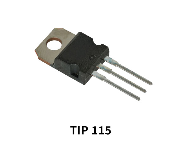
The TIP115 is a popular NPN Darlington transistor. Here's the information you requested:
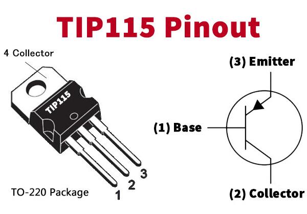
Pinout:
The pinout configuration of the TIP115 transistor is as follows:
- Base (B)
- Emitter (E)
- Collector (C)
Equivalent Transistors:
The TIP115 transistor does not have direct equivalents, as it is a specialized Darlington transistor. However, similar Darlington transistors that can be used as alternatives include:
- TIP110
- TIP112
- TIP121
Please check the datasheets of these transistors for detailed electrical characteristics and pin compatibility.
Features:
Here are some key features of the TIP115 transistor:
- Polarity: NPN (Negative-Positive-Negative)
- Power Dissipation: The maximum power dissipation of the transistor is typically around 80 Watts.
- Collector Current: The maximum collector current (Ic) that the transistor can handle is approximately 5 Amperes.
- Collector-Emitter Voltage: The maximum voltage that can be applied across the collector-emitter junction is typically around 60 Volts.
- Darlington Pair: The TIP115 is a Darlington transistor, which means it consists of two bipolar junction transistors connected in a way that provides high current gain and reduced saturation voltage.
- High Gain: The TIP115 has an extremely high current gain (hFE) of up to several thousand, enabling it to amplify weak signals or drive higher loads.
- Fast Switching Speed: The transistor possesses a fast switching speed, which makes it suitable for applications requiring quick switching between on and off states.
Applications:
The TIP115 transistor finds applications in various electronic circuits, including:
- Power Amplification: It is commonly used for power amplification in audio amplifiers, where high output power is desired.
- Motor Control: The TIP115 can be used in motor driver circuits to control the operation of motors in applications such as robotics or industrial automation.
- Relay Drivers: It is suitable for driving relays, allowing switching of higher loads using lower current control signals.
- Solenoid Control: The TIP115 can control solenoid valves and actuators used in applications like fluid control and automation.
- Power Supplies: The transistor can be utilized in voltage regulators and power supply circuits for control and switching purposes.
- Lamp Drivers: It is employed in lamp driver circuits for controlling lighting elements such as LEDs, bulbs, or fluorescent lamps.
Usage Recommendations:
When using the TIP115 transistor, consider the following recommendations:
- Heat Dissipation: The TIP115 is capable of handling higher currents and power dissipation. Adequate heat sinking or thermal management may be required to prevent overheating.
- Drive Voltage: Ensure that the base current and voltage are sufficient to drive the transistor into the desired operating region. Refer to the datasheet and transistor characteristics for appropriate control signals.
- Safe Operating Area: Keep the operating conditions (voltage, current, power) within the transistor's safe operating area (SOA) as specified in the datasheet.
- Protection Diodes: Depending on the application, consider adding protection diodes, such as a flyback diode or freewheeling diode, to safeguard against voltage spikes and inductive loads.
Please note that the information provided is based on general knowledge and the available information in my database. It's always recommended to refer to the transistor's datasheet and consult with design references or experts in the field for precise usage guidelines and specific circuit requirements.